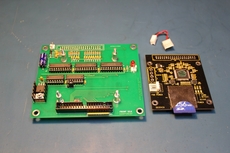
astrorat.com
The Current Retro Elf Project Release
Retro Elf Plus
In 1976 a team of RCA engineers led by Jerry Herzog released their second microprocessor the CDP1802. It used RCA’s CMOS process called COSMOS (Complementary Silicon/Medial-oxide Semiconductor). The CPD1802 was the single chip successor to the earlier two chip 1801 design. Like the 1801 the 1802 incorporated the COSMAC (Complementary Symmetry Monolithic Array Computer) architecture developed by Joseph Weisbecker in the early 1970s. 

One of the items I have had on my bucket list for many years now is creating a complete computer design based around the RCA CDP1802 microprocessor.  My vision, to create an 1802 based computer system with the look and feel found in the vintage computers in the 70s. Something similar to the original Altair 8800 released in the mid 70s. These early computers used simple lights to show the current memory address, output data and to monitor system status. You controlled the system using toggle switches for system control, address and data inputs. 

Back in “the good old days” you sat in front of your system and manually toggled in programs via the toggle switches and hopped to get the results you were looking for on the many lights.

In the end I ended up creating a two board solution.  The first board is the main CPU. It contained everything needed to run as a standalone unit. The second board contained all the electronics needed to create an optional front panel for user interface. The front panel would allow the user to program, monitor and control the operation of the system like days of old.
Retro Elf Tunekey Version
Don't want a front panel, no problems, here is the turnkey version of the Retro Elf. This Elf will boot up in to a ROM monitor that receives user inputs via a VT100 terminal connected to the DB9 supporting COM1. From the monitor you can do basic debugging or BOOT to Elf/OS. From Elf/OS you can run RCBASIC, SuperBASIC or any number of Elf/OS applications.

I created a 3D printed case to hold the Retro Elf stack of boards, power supply and the three DB9 serial connections. The case was designed to allow the use of two acrylic panels to be slid in to the top and bottom of the case. All the debugging LEDs are viable though cutouts in the sides or through the clear acrylic panel at the top of the case.


Only the front panel PC board is missing from the turnkey unit. The board stack contains the RetroElf2 64K CPU board, the expansion board and the ATA/IDE storage board.
Under the cover of the current Retro Elf Plus
Inside of the Retro Elf Plus
CPU Board

The CPU board is not depended on any other boards in the Retro Elf System allowing use in standalone applications. Here is located the heart of Retro Elf, the CDP1802 microprocessor and its supporting electronics.
 
The design uses low power CMOS components to help keep the board’s power needs to a minimum. A simple on board 5 volt DC voltage regulator is implemented to power the complete system (CPU and front panel). This regulator can supply 5 volts at up to half an amp when an 8-12 volts DC input is supplied to the board.  A protection diode is used to help protect against accidental reversal of input power.
 
The system clock is provided by an on board oscillator module. The labeled oscillator module frequency is divided by two before entering the 1802.  So if the oscillator is rated 6MHz the 1802 would see 3MHz. One interesting feature of the 1802’s CMOS architecture is the capability to operation at any frequency from DC up to the processor’s rated frequency.  You can even very the frequency at any time. A future add-on board is planned to take advantage of this feature. You can adjust the processor frequency during operation allowing you to see each fetch and execute cycle operation of running code via the front panel.
 
All 64K bytes of supported memory has been split in to two 32K chunks and have been addressed in to two chip sockets.  On-board jumpers provided configuration for each of the two sockets as needed.  The most common default setup has a static RAM in the first socket addressed from 0000H to 7FFFH and EEPROM/EPROM used the second socket addressed from 8000H to FFFFH.
 
An on board “boot-strap” circuit is provided. When enabled, the 1802 is tricked in to start running code from 8000H after a clear (reset). A jumper selectable boot-strap clear signal can come from either a high on the 1802’s Q line or any I/O operation.

An optional on-board battery backup circuit is also implemented to provide 3V DC to SRAM when normal power is lost. The use of a low power CMOS SRAM should be used to allow for a normal standby battery life.

Simple software (bit-banging) serial can be provided using the 1802’s Q output line and one of the four jumper selectable EF input lines.  Both the serial input and output can be setup as normal or inverted again via on board jumpers.  A MAX232A integrated circuit is use to create standard RS232 signal level on the serial lines. This allows for easy connection to most terminals or computer serial ports supporting RS232 signaling.

The 40-pin expansion header brings out most of the 1802’s signal lines as well as a 5 volt DC power source. It is via this header that the front panel will be connected in addition to any other future expansion boards that my come.

Two groups of status LEDs have been provided to indicate operational status of the CPU board. The group of four LEDs provide status on the boot-strap circuit, the +5VDC power, serial RXD and serial TXD (aka 1802’s Q LED). The group of three LEDs provide processor status; RUN, WAIT and RESET. If all three LEDs are off the microprocessor is in a LOAD mode not normally seen while in standalone operation
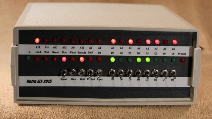
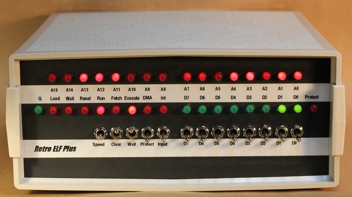
Front Panel

The front panel is connected to the CPU board via a 40-pin flat cabled.

The front panel gives the user a window in to the operations going on within the 1802. Key information is provided via LEDs that monitor the memory address, processor state (fetch, execute, DMA or Interrupt) and process mode (load, wait, reset and run). An additional eight LEDs are used as an output port.
  
12 toggle switches are used for system control and data input. Four switches handle Clear, Wait, Memory Protect and Input. The remaining eight switches are used for user data port input OR data to be written to the current memory location while in processor load mode. The Input toggle switch is a spring return type returning to the down position for each operational cycle for the switch.

Expansion board

When the expansion board is installed in to the Retro Elf system, it is plugged in to the CPU board via a 40-pin header socket placed on the bottom side of the board.  This creates a board stack between the CPU and the expansion board. The front panel is then plugged in to the expansion board using the 40-pin CPU board pass-through connector.

The expansion board increase the number of features available to the Retro Elf Plus system. A simple on board 5 volt DC voltage regulator is implemented to power the expansion board. This regulator can supply 5 volts at up to half an amp when an 8-12 volts DC input is supplied to the board. A protection diode is used to help protect against accidental reversal of input power. Four jumpers are provided to select how the Retro Elf system will be powered. The complete system (CPU, front panel, slow clock board and expansion board) can be powered by ether the CPU’s or expansion board’s on board regulators. In some cases you may need to power the CPU, front panel and slow clock board separately from the expansion board. These four jumpers allow the flexibly to setup the power needs for each application.

Two COM ports using 16550, high speed, serial UART chips are implemented. Each COM port is interfaced using a MAX232A integrated circuit to create standard RS232 signal level on the serial lines. This allows for easy connection to most terminals or computer serial ports supporting RS232 signaling. Both COM ports support hardware handshaking to allow for the fast as possible transfer of serial data. Two jumpers for each of the COM port channels are used to select if DTR/DSR or RTS/CTS pairs signaling will used to support handshaking. Four diagnostics LEDs are provided for each COM port channel that show the status of TX, RX and both handshake lines.

A 40-pin header is supplied that conforms to most of the standard ATA-3 specifications and supports pretty much any ATA device that conform to: a. Support for 8-bit transfer mode. b. Support for logical block addressing (LBA) mode. This connector can be used to attach an external device like disk drives or many versions of Compact Flash cards that meet the above requirements.

A four pin header is also supplied that allows the addition on streaming external interfaces that support the use of an audio tape recorder or streaming floppy to save programs.

Real-Time-Clock support is provided using an Epson RTC72421 module. This RTC module provides highly accurate time-keeping and supports time and date for hours, minutes, seconds, month, day, year and day-of-week. An on board backup battery provides continues operation of the RTC even when no power is being supplied to the Elf. The RTC can also be programmed to supply fixed-period interrupts to the Elf system.

Power supply

Power needs for the Retro Elf unit are supplied nicely by a small enclosed 12 volt switch power supply. The selected supply is rated at 25 watts and can be plugged in to most mains power from 88 to 264 VAC at 50/60Hz. The power supply I have been using is the TDK-Lambda LS25-12 which is available from Digikey. Us the following link for more details:
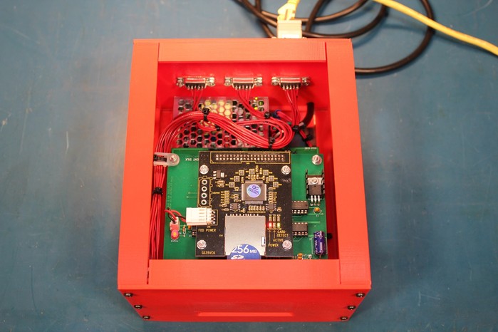

Enclosure

I need to point out that this website indicated that I used a C-350 series enclosure. This was an error. The actual enclosure is a PacTec "C-325 Kit" (PN: 61866-510-039-6) and measures 9.2 x 8.5 x 3.6 inches. I have bought all my PacTec boxes directly form PacTec. Use this link for more information on the C325:
A small 12 volt DC fan is installed on the back case cover. This fan helps provide air flow through the case to keep everything cool while the Retro Elf is in operation. Bench tests seem to indicate that given the low power needs for the CMOS electronics, the fan may not be needed. But I like to be safe so I have kept the fan in the final design.

The current pictured front and back panels shown above came from Front Panel Express. They have design software that can be downloaded and installed that will help create nice looking panel designs. You can find their information here:

New - Adding SD card support to emulate up to a 250Mb ATA-3 / IDE hard drive

In the course of developing the Retro Elf system, it was clear to me from the start that some form of high capacity internal storage would be needed. Back in the good-old-days when the CDP1802 processor was being released, data storage was normally handled by some form of magnetic media. Like many of the system out during the 70's, the COSMAC Elf hobbyist most likely used cassette tapes. Some more advanced systems used streaming floppies, 8-inch or 5 ¼-inch floppy disks.


For the Retro Elf, the storage goals where based around some form of internal storage system. 


The final design centered around mimicking a classic ATA / IDE hard drive interface. While the ATA / IDE standard would became popular later in the 80s, this drive interface allowed me to fit a storage system in to the tight space within the Retro Elf's case thus eliminating the need for a second external box.


When coupled with Mike Riley's Elf OS, the resulting storage system could provide a maximum capacity of 268,431,360 bytes. More than enough to support all the Retro Elf's storage needs. 


The resulting digital storage system is based around two PC boards. The first being one of the many standard off-the-shelf SD card-to-IDE boards out of China. These boards cost from $6 to $20. The second board would allow the selected board to interface to the Retro Elf's IDE connector on the Expansion Board.

The first of the two boards used to make up the Retro Elf's digital storage solution, is an off the shelf, SD card-to IDE board. The selected board was out of China and costs ~$9 and was easily found on Ebay, Amazon and many other web sites.

For use in the Retro Elf, these boards needed to be modified from the form shipped. The 40-pin IDE header needed to be removed and replaced with a 40-pin connector that was soldered under the board.

This allowed the boards to be part of the board stacking system found in the Retro Elf design.

For me, making this change was greatly simplified with the use of my desoldering station. While I was removing the 40-pin header, I also removed the 4-ping Molex power connector since I would not be using it.

Removing both the header and 4-pin connector and adding the new 40-pin connector, takes me only about 10-15 minuets. 

The down side with using many of the SD card-to-IDE interfaces was the use of a 3.3-volt logic system. Just plugging many of these board straight in to the Retro Elf's IDE harder would produce frustrating, intermittent results and outright data loss.
The second board in the Retro Elf's storage system is the interface board between the SD card-to-IDE board and the ELf's IDE connector on the Expansion board.

The Retro Elf ATA/IDE Interface board performs three operations:


  1. Provide a stable +5-volt DC power source. that will be regulated down to the needed 3.3-volt on the SD-to-IDE board on board regulator.
  2. Provide a digital level conversion interface between the Retro Elf's 5-volt logic and the SD-to-IDE board's 3.3-volt logic output.
  3. Reduce the high frequency logic switching noise floor found on the Retro Elf to a point that the 3.3-volt input logic on the SD-to-IDE board is not influenced by false digital triggering. 
As seen above, the finished project fits nicely on top of the Retro Elf board stack.

Currently I am testing several of these boards to compatibility and stability. There are three test board running at the Astrorat labs. One board is installed in the Retro Elf Plus featuring the classic CPU board. A second board is installed in the Retro Elf Plus featuring the 64K shadow ROM CPU board. The final board is connected to my Spare Time Gizmos' Elk 2K system.
The IDE to CF interface module
As several Retro Elf builders have noted, the Retro Elf pictured above includes a IDE to CF interface module that is plugged in to the 40-pin IDE ATA-3 connector. This has generated several emails requesting details.  I will try and answer the three most common questions I have received.

Q1 - What is the IDE-CF interface module you are using?

The one pictured came from Amazon and is labeled QNINE - CF Card to 3.5" IDE Female Adapter and cost ~$9. There are many cheep IDE to CF modules and the price and types change all the time. I myself have been buying whatever is cheep on Amazon or eBay. These modules are pretty simple and most should work.


Q2 - Where did I get the 40-pin 90 degree connector used to plug the module in to the 40-pin header on the expansion board.

The 40-pin right angle connector used was fabricated. from the same connector used to connect the CPU and Expansion boards (Digikey# 1528-1385-ND).


Given that the above connector has long straight pins, the 40-pins need to be bent so that one row of 20-pins will be at 90 degrees close to the connector housing. The second row of 20-pins also need to be bent to 90 degrees but care needs to be taken so the resulting spacing between the two rows of 20-pins is about 0.1 inches.

As seen in the included picture above, I used a piece of 0.1 x 0.1 hole spacing prototype board as a tool to help me bend and space the pins. I cut the board so that at least 20 holes on the edge of the board were cut through the middle of that row of holes.

First just use the tool board to help simply bend the first row of 20-pins to 90 degrees close to the connector's housing.
Next place the 20-pins of the second row needing to be bent in the row of hole just above the ones that where cut through on the edge. Bend the second row of pins until the first row of pins come up and inserts in to the half cut holes as shown.

This should result in two rows of 20-pin with a 0.1 spacing. Trim the first row of pins as need to match the second shorter row of pins just bent. Now plug the newly created adapter in to the IDE-CF card's
connector and that assembly in to the IDE on the expansion board.

Q3 - What OS are you using.


The OS I have been integrating in to my Retro Elf systems is Mike Riley's Elf/OS. Details can be found at Mike's web site at http://www.elf-emulation.com/elfos.html.

While the Elf/OS works, in my opinion there is still a lot more work to be done. Mike has not done much with Elf/OS since 2008.  I patched both the RCBasic and RC Elf/OS to work with the Retro Elf. There still is room for some software guru types to update and enhance what is there if anyone is interested in taking on such a project.
Behind the Retro Elf Plus
Retro Elf Plus revision D Backside
A look at the backside of the Retro Elf Plus reveals a simple and clean layout.  Here you find the main power cord along with three RS232 serial ports used to interface the Elf to terminals and printers. The serial 1 supports the original "bit-banging" (software defined using the 1802's Q output and one of the four it's EF input line) with speeds up to 4800 baud. Both Serial 2 and 3 are based on the 16550 (8250)  UART integrated circuit. These ports support much higher baud rates and hardware handshaking.

The backside also provides ventilation holes and fan support to help keep the electronics inside the unit tuning cool.

Designing, Building and Testing
Both the CPU and front panel went through several design tests. Here is the prototype build of the CPU board along with the bread board phase of the front panel.  By this time I had already finalized the revision B CPU board and had picked the enclosure I planned to use in the project.
Adding an Expansion Board
Retro Elf Expansion Board
Retro Elf Revision A Expantion Board
From the beginning, there was a plan to develop an expansion board. This board would add extra features to the original Retro Elf design.

One of my major requirements was the inclusion of a hardware serial port with handshake. This port needed to support higher baud rates for faster screen refreshes and quicker file transfers. The 16550 UART integrated circuit became the heart of the high speed serial port. In the end, I ended up designing in two 16550 UARTs on to the expansion board.

The serial ports also needed to support the standard RS-232 signaling levels. This was achieved using the MAX232 interface integrated circuit.

To help with serial port debugging and keeping with my many cool blinking lights theme, each serial port included four LEDs that monitors the data input/output lines as well as the two supported in/out handshake lines.

As seen in the above picture, I am adding a battery backed up Epson RTC-72421 Real Time Clock module to the design. This RTC module will gives the Retro Elf a hardware time and date clock feature.

A 40-pin, 8-bit IDE header is also provided to allow the interfacing of external storage devices.

Like days of old, a four pin header is provided to support an external cassette tape storage system. Given the number of tape interface systems there where in the past, the four pin header only brings out +5 volts DC, a driven output on the 1802's Q line and a jumper selectable input to one of the 1802's EF inputs. So some form of appropriate external tape interface will be required to meet your specific needs. 

While the power needs for the expansion board can supplied by only the CPU boards voltage regulator circuit, I also added a second voltage regulator section on the expansion board.  Four jumpers allow you to configure the expansion board to be powered by the the CPU's regulator or run with it's on board voltage regulator.  It is even possible to power the Retro Elf's front panel via either the regulator circuits.
The Slow Clock
Restro Elf with Prototype Slow Clock Option
As mentioned earlier, one of the interesting features of the Retro Elf's CMOS construction is the ability to adjust the clock speed at any time to any rate. Here we see the first bread board stage for the Slow Clock option designed to take advantage of this.

This system is NOT a single step operation where the 1802 clocks a full speed through fetch and execute and then waits at the end of the cycle for you to say another step please.

A slow clock feature is a great way to both debugging hardware and software.  It also allows you to see how the 1802 process code.  You will discover that the address LEDs no only display the address of the next memory operation but also the 16 bit data being moved from internal registers. So a decrements of an internal register will show up on the address LEDs during the execute phase and then return to the next memory location on the next fetch.

I have used the above prototype clocking systems in classes to show students the inner workings of their code. For me, it is exciting to see the lights go on in the student head as the LED lights reveal what going on inside the Elf as it step through their test code.

Originally I was going to use a 555 timer IC but ultimately went with a dividing of the system clock.  The resulting design uses a three position toggle switch with the same look a feel as the toggle switches already in place on the front panel of the Retro Elf. In the up position, you get full clock speed normally 3Mhz.  In the second, middle position, the system clock is divided down to ~183Hz. With the toggle set in the down position you get the lowest speed of ~3Hz.

Testing showed that the middle speed was just fast enough to push through code but still get some useful indications from the status LEDs.  The slowest speed gave you the time to really watch each clock cycle happen.

In reality you can use jumpers to select one of four frequencies for both the middle and down positions. If you wish, you can reverse the order so that the middle position is very slow and the bottom is the faster speed. It is even possible to make both middle and bottom the same clock speed! The following table shows each of the four possible setting when a 3MHz master clock is used:

Jumper 183Hz 46Hz 11Hz 3Hz
A0 Out In Out In
A1 Out Out In In
Enhancing the Front Panel
At the 2016 Vintage Computer Festival Mid-West, fellow Elf enthusiast Josh, was showing me his version of the Retro Elf he just completed for the show. In his resulting unit he incorporated three nice enhancements that I felt needs to be added to the overall Retro Elf Plus project.

In the above picture, all three changes are implemented for testing. A small protoboard has been added the above revision B of the Front Panel.

Josh's first modification added a AND gate to address display latches. This required both the TPA (Timing Pulse A) AND SC0 (State Code Zero) conditions to be true in order to latch the eight high bits of the address. Likewise both the TPB (Timing Pulse B) AND SC0 conditions are required to be true to latch the eight low bit of the address. The results of adding the SC0 signal is that latched and displayed address are only memory read/writes and not that of internal processors register manipulations. This results in a cleaner display of the address currently being executed.

Josh's second modification routed the decoded RUN signal out of the processor's operational mode decoder display circuit in to the processor's state code decoder display circuit. This mod will only indicate the processors current State Code only while it is in a running.

Josh's final change added logic to display the current instruction being executed on the data LEDs while the Retro Elf is using the Slow Clock option.  This is particularly nice when you are debugging code and wish to see what instructions the processor is currently executing.
Adding Shadow ROM to the CPU Board

Another idea I have been working on is the addition of a Shadow ROM circuit. The above CPU board is the first attempt of an implementation of this concept.

The Shadow ROM concept is simple. When the system is first booted, the ROM monitor is running from the on-board ROM. The ROM monitor does any power on self tests needed and then copies itself in to RAM that is addresses in the same physical location as the ROM.

This magic is accomplished by allowing any memory reads to come from the ROM after boot up and any writes will go only to the RAM located at that same address range. Copying is then a simple matter of read the ROM byte from the current memory location and writing that byte back to RAM again the same memory location.

Once you are done coping any needed code from the ROM in to RAM, you then write to a specified output port that disables the ROM requiring all future reads and writes to come for the RAM.

The nice feature of having Shadow ROM is once you turn off the ROM you get a full 64K or RAM to use with any running applications in memory.

There is a down side to the above implementation, there is no power-on booting. You need to use the Retro Elf's front panel to point to the location of any ROM monitor code to be executed.
Retro Elf ROM firmware
◊Retro Elf Plus ROM firmware version 1.13 build date 10/15/2016 for systems using a Classic CPU board.

◊Retro Elf Plus ROM firmware version 2.05 build date 6/2/2017 for systems using a CPU 64K board.

◊Patched version of the origianl Elf 2000 ROM firmware version 88B which fixed the RCBASIC GOSUB bug.
The Original Version A - Retro Elf 2015
Revision B - Retro Elf 2015
Revision C - Retro Elf Plus